Measuring Heart Rate on LCD using PIC

Measuring Heart Rate on LCD using PIC 
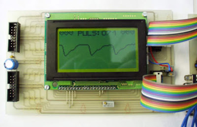
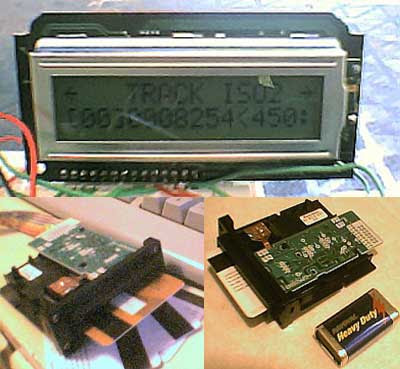
Did you know that The human heart can be measured optically. The heart beat with the varying blood pressure leads to a measurable change in the visual content of peripheral blood vessels. This is as good at the finger detect. There are two project work available, which were so far advanced that the optical signal pulse seized on a liquid crystal display graphically. Both works have been with a microcontroller PIC16C74 to collect and visualization of the signals.

Pulse measurement in a light
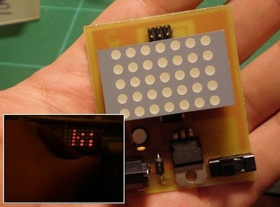
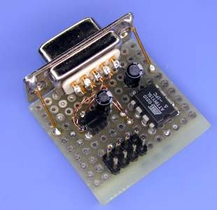
The light source was a red LED superhelle. The finger penetrating light was a light-frequency converter TSL230 detected. The period of the signal from the TSL230 was using the capture of the micro-controller unit with an accuracy of about 15-bit recorded. Through digital filtering 50Hz interfering signals were suppressed and the pulse signal extracted.

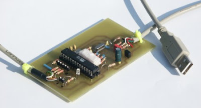
Pulse measurement in reflection
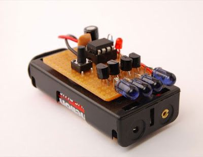
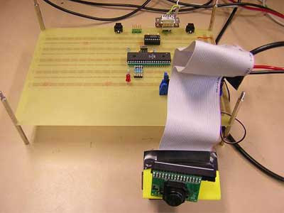
For the lighting of the skin's surface, an infrared LED used. the censor use PIN photodiode. With an analog circuit filters were equal light and high frequency interference signals eliminated. The signal was pulse by the A / D converter of the microcontroller with 8-bit digitized.

[Link]

LCD SWR Meter using PIC 16F88

LCD SWR Meter using PIC 16F88Measuring SWR at VHF/UHF frequency was never a fun. Most radio amateurs just assume that their 50 ohms cable is matching a beam or GP.

LCD SWR Meter presented here meet many simple task using a microcontroller PIC16F88. The very basic purpose to make this project is to encourage radio amateurs to build their own High Quality LCD SWR Meter at low price, instead of buying expensive ready made units.

[link]

Atmega168 RDS decoder

Atmega168 RDS decoder
This decoder is fed by a RDS demodulator IC (or tuner) which has RDDA (data signal) and RDCL (clock signal) outputs.The microcontrolller is an Atmega168 clocked on the external 4.332MHz crystal from the RDS demodulator. TDA7330B RDS demodulator IC from STMicroelectronics to be used in this project. The TDA7330B is connected to the Atmega168 with RDDA connected to PD4 (on PORTD) and RDCL to INT0 (PD2).


The software in the Atmega168 is able to decode the following RDS data:

* Programme Identification code (PI: 0x83C7, Detected new station.)
* Program service name (PS: RADIO538)
* Programme Type code (PTY: 0x0A, Pop Music.)
* Traffic Programme Identification code & Traffic announcement code (TP&TA: 0x01 0x00, Traffic announcements available on this station and maybe via EON on another station.)
* Music Speech switch code (MS: 0x01, Music is being broadcasted or station does not use MS flag.)
* Decoder-identification control code (DI: 0x01, Stereo, Dynamic PTY.)
* Alternative frequency codes (AF: 0x98, 102.7MHz.)
* Linkage Actuator (LA: 0x00)
* Extended Country Code (ECC: 0xE3)
* RadioText (RTA: Radio 538 = Randstad (Zuid) 102.7 FM)
* Clock-time and date (CT: 0x1A53CD844, UTC 2006-07-02 (MJD 53918) 13:33:00 +02:00, TIME 15:33:00)

Download for document, source code here (zip)
[link]

Serial interfacing LCD with PIC Microcontroller

Serial interfacing LCD with PIC MicrocontrollerParallel interfacing LCD with MCU at least need 6 I/O pins (4 bit mode) and maximun can up to 11 I/O pins (8 bit mode). The I/O pin can be cut down to 3 pin by serial iterfacing using shift register. They were few shift register can be used such as 74HC164, 74HC595, CD4094 and any compatible 8 bit shift register. Before you attempt to do serial interfacing, it is good pratice to familiar with parallel interfacing. You can find many reference from internet.Following diagram show the serial interfacing Hitachi compatible 2 X 16 LCD modules with Pic16F84 or Pic16F628 MCU.

Download documentation and source code for serial interfacing LCD with PIC here (zip file)
[link]

Net Radio


The Net Radio created by Bertrand Achard. The Net Radio enables you to listen to MP3 streaming radios that are broadcast over the Internet without a PC. MP3 streams are received through an Ethernet link, decoded by an on-board MP3 decoder, and then output as audio through a 3.5-mm stereo jack. The user-friendly design includes easy-to-use switch buttons and a color LCD. The Net Radio is designed around an ATmega64L RISC microcontroller that provides ample memory. The ATmega64L was also chosen for its low power consumption, which enables the Net Radio to be interfaced with low-power commercial devices.

Link : Source | Abstrak | Entry

Ping-Pong using ATmega8535

Project description:
Another cool project from course ee476 Cornell university that used an Atmel AT90S8535 microcontroller for Ping-Pong project. It used the ADC on the chip to read the positions of the potentiometer controllers (see Hardware). The game is for two player simultaneous play, although it is also challenging and fun to play against your self using both controllers.

Link : Ping-Pong using ATmega8535

USB Audio Card

The USB Audio Card project offers a better solution than going through the hassle of adding a new PCI audio device to a PC. A high-speed USB and a powerful ATmega162L-8PI microcontroller are the keys to an easier upgrade. A USB B-type-to-A-type cable is used to connect the audio card to the PC. Windows pretty much handles the rest of the work. With earphones connected to the card, you can listen to MP3 and WAV files. This cool project made by Havent Chen

Link : USB Audio Card | Abstrak | Entry

RF remote control using microcontroller AVR


Using remote control make our work more easier. like turn off Air conditioner, change channel TV, play your home theater and more. There are many type of remote control like Infrared, Radio Frequency, SMS and more. To control device behind the wall like garage door you can only use Radio Frequency remote control. Because the other can not bypass the wall.

Here is RF Remote control using microcontroller created by serasidis. There are two part in this electronic project : transmitter and receiver. The transmitter is constituted by AT90S2323 microcontroller and TLP434 RF transmitter module at 418MHz. the transmitter designed for battery economy use and safe transmition of the data. The receiver constituted by RF receiver module RLP434A at 418MHz, the microcontroller AT90S2313 and the 2 relays with can handle any electric (or electronic) device up to 10 Amps (the contacts of my relays are 10Amp at 250Volts).For antenna you can use a cable 30 - 35cm long.

Download here for documentation, firmware, source code and schematic.
[link]

Holographic Information Systems Thesis

Holographic Information Systems Thesis
The goal of this work is to investigate the use of holographic techniques for information processing and transmission systems. Until recently information has been processed and transmitted mainly electronically. With the advent of optical fiber communications the monopoly of electronics has receded in the telecommunications field, but the domain of information processing is still dominated by electronic processors.

This thesis follows a top-down approach to the design of processors that integrate both electronic and optical components. It begins with the design considerations of a compact, rapidly reconfigurable opto-electronic processor, which possesses an optical bus in addition to the traditional electronic bus. The optical bus takes advantage of the massive parallelism that is afforded by optics and can be coupled to a holographic digital memory, allowing rapid reconfiguration of the device. The capability of rapid reconfiguration gives rise to a new computational paradigm, where the reprogramming of the device can become part of the computation. We suggest additional applications of this processor, namely as a smart reading head for large scale holographic disk memories. Finally we present novel algorithms that were developed specifically to take advantage of the additional capabilities of our processor. The next section is concerned with the wavelength and angular tuning of strong volume holograms, both in the reflection and 90-degree geometries. Since photons have no charge, we need to rely on their wave properties to manipulate them, both for long-range transmission, such as telecommunications, and short-range transmission, such as on chip interconnects. In this section we investigate how volumeholograms can be used to selectively redirect information bearing light beams.

The final part of this thesis is concerned with material issues. Holographic recording of strong volume gratings is one of the most commonly used approaches, and photorefractive materials have a strong bearing on the overall performance of the final system.

Download this thesis

RF and IR Remote Control

PIC remote control IR and RF
This PIC based remote control allow you to control up to 8 devices by this easy constructable remote control. The project very flexible you can use it as radio remote control or infrared remote control, depending on the components. Each device output can be configured to be momentary (turned on while you press the button) or latched. Latched outputs can be toggled on/off by one button per channel, or turned on and off by two buttons per channel.

tag : IR remote control, RF remote control, wireless project control
[link]

PS to USB Joystick Converter

PS to USB Joystick Converter
If you have PS 1 or PS 2 joystick and you want use it for USB. Well this microcontroller project could resolve your problem now. PS2USB converts two Playstation 1 or Playstation 2 converter into usb josysticks. It also features the Dance Pad Code (Up+START+SELECT), so that it can be used in DDR games (tested with Stepmania). Works under Linux, Mac OSX, Windows.
note : no picture for the project, i just replace it with analog PS 1 joystick
Download :
source code and schematic

search term : PS to USB, Converter, Microcontroller Project (src)

Electronic Tools : Weller WLC100 Soldering Station

Weller WLC100 Soldering Station
Soldering Iron is a must have tool for electronic engineer or Hobbyist. Choosing good soldering iron can make your electronic project designing process faster and have good result in circuit connection.

The Weller WLC100 Soldering Station includes everything you need to start using solder to join metals and create efficient, electrical connections. Designed with the hobbyist and the do-it-yourself enthusiast in mind, this kit features a high-quality, lightweight pencil iron with variable power control, a cushioned foam grip with a replaceable heating element, and a safety guard iron holder. And it’s from Weller, the world leader in soldering since 1945.

Scroller 7 × 5 LEDs based on Attiny2313

Scroller 7 × 5 LEDs based on Attiny2313Cool microcontroller project from kalinda. In this project he used microcontroller AVR Attiny2313 that is perfect for controlling the 13 pins required for the matrix of LEDs. he has also provided pins in the most optimal order to occupy as little as possible.

List of materials

  • Programmer for AVR micros (AVRisp MKUII in my case)
  • Microcontroller Attiny2313 with fuses configured for internal oscillator 8Mhz
  • 1x Display 5 × 7 leds Kingbright
  • 1x voltage regulator 7805
  • 1x battery or source of food 9v
  • 2x Capacitors 100uF
  • 2x Capacitors 100nF
  • 5x Resistances 90 Ohms

Required Software

Drawings and plates

[link]

USB AVR Programmer STK500

USB AVR Programmer STK500In this microcontroller project, Guido Socher design a state of the art USB programmer for the AVR microcontrollers from Atmel. The programmer firmware has no device dependent data. Therefore it works for almost any AVR microcontroller on the market and possible future microcontrollers.

This USB programmer has, unlike other programmers, no "chicken and egg problem". That is: you can build it from scratch without the need of another programmer to load the initial firmware.The firmware is open source and programmed in C according to the AVR068 specification from Atmel.

[link]

AVR Infrared Link Project

AVR Infrared Link ProjectThis AVR microcontroller project created by Sivan Toledo. In this project he created an infrared (IR) link that provides bi-directional communication between the NXT and the new Power-Functions system, which consists of a battery box, motors, a remote control (an IR transmitter) and an IR receiver that controls the motors.

He previously built an IR transmitter for the NXT which used an MSP430 microcontroller and which was able to send Sony IR commands. In this project, he wanted to achieve three additional goals:
  • To analyse the Power-Functions IR protocol.
  • To build a system that could not only send IR commands, but could also receive and decode them.
  • To experiment with AVR's, another family of microcontrollers.
But for this project he tried to use AVR Microcontroller. Compared to the MSP430 microcontrollers, the AVR family offers many more chips in DIP packages, they run at wider supply voltages (most can tolerate at least 2.7-5.5V and some operate down to 1.8V), and their pins can supply a lot of current (up to 40mA for a single pin). The wide range of supply voltages means that they can be connected to the 4.3V supply of the NXT's ports directly without a regulator, and the ability of the pins to supply a lot of current simplifies some circuits, such as when the chip needs to drive a bipolar transistor or a LED. Another advantage of the AVR is that they can be programmed using a wide variety of simple circuits, not just with proprietary programming devices.

[Link]

Digital Clock with PIC16F84A

Digital Clock with PIC16F84AThis is a small ajustable clock based on microcontroller PIC16F84A microchip.The electronic project here is very simple because the hardware only uses 74hct238 demultiplexer, 4x7 segments, and some resistors. The software is programmed through a device connected to serial port with icprog and made/debuged with MPlab. For PIC Programmer you can use JDM PIC16F84A programmer.

[link]

Serial Port IR Receiver Using AVR

Serial Port IR Receiver Using AVRAnother cool microcontroller project created by Klaus Stock. He said, this is a simple IR receiver circuit which plugs into a serial port of a computer. This circuit has two major advantages:

1. it uses an Atmel AVR RISC microcontroller (an AT90S2313) instead of the usual PIC microcontroller and
2. it uses a Maxim MAX232 for the generation of valid RS232 levels.

Advantage 1 is, of course, only valid for all those AVR addicts which have this device (and the corresponding programmer) ready at hand and don't care about PICs and PIC programmers. Advantage 2 comes into play if the IR receiver has to placed at a great distance from the computer; the MAX232 is more likely to deliver valid signals over bigger distances than cheaper solutions.

[Link]

Serial interfacing LCD with PIC Microcontroller

Serial interfacing LCD with PIC MicrocontrollerParallel interfacing LCD with MCU at least need 6 I/O pins (4 bit mode) and maximun can up to 11 I/O pins (8 bit mode). The I/O pin can be cut down to 3 pin by serial iterfacing using shift register. They were few shift register can be used such as 74HC164, 74HC595, CD4094 and any compatible 8 bit shift register. Before you attempt to do serial interfacing, it is good pratice to familiar with parallel interfacing. You can find many reference from internet.Following diagram show the serial interfacing Hitachi compatible 2 X 16 LCD modules with Pic16F84 or Pic16F628 MCU.

Download documentation and source code for serial interfacing LCD with PIC here (zip file)
[link]

Multifunction Digital Thermometer

Multifunction Digital ThermometerThis instructable will show you how to create a multifunction platform with a thermometer, chronograph (count up timer), count down timer, and light display. It is also intended to be a platform for other analog sensors or any other functions you can think of. Project is based on Atmega168 microcontroller. Information is displayed on dual 7 segment LED display.

Multifunction Digital Thermometer [link]

Simple Metronome Project

Simple Metronome ProjectDaniel designs this Metronome with a few simple electronic components.The Metronome is any device that produces a regulated audible and/or visual pulse, usually used to establish a steady beat, or tempo, measured in beats-per-minute (BPM) for the performance of musical compositions. It is an invaluable practice tool for musicians that goes back hundreds of years.


Material Needed:

Simple Metronome Project

1. 555 IC
2. 3x 1K Ohm Resistor
3. 2x 22uF 16V Capacitor
4. 9V Battery
5. 8 Ohms Speaker
6. 250K Ohms Potentiometer

[link]

AVR Temperature Meter

This is a four-channel temperature measurmet adapter that works without external power supply. It will suitable for measureing temperature and logging its data with a PC. The circuit diagram is very simple and no adjustment is required, everybody will able to build it with ease. These great project created by ChaN.

AVR Temperature Meter

"I chose an Atmel ATtiny15L for this project. It is the only device that has a built-in 10bit A-D converter in the 8 pin AVRs. The A-D converter has a bandgap reference and differencial amplifire as its front-end. The AVR core is clocked by only internal RC oscillator (calibrated to 1.6MHz), any other clock souce cannot be used. Also 25.6MHz clock source that 16x multiplied from core clock is available for timer/counter. This means that a fast PWM output can be generated. Therefore the ATtiny15L has good analog I/O capabiltity.

In this project, the A-D converter is used as four channels, single-ended, no gain and VREF from Vcc configuration. However RSTDISBL fuse must be programmed in order to use pin #1 as one of the analog inputs, an AVR programmer that can program in HVS mode is required."

For documentation, schematic dan code, download here


[link]

Interfacing DRAM Memory with AVR

Interfacing DRAM Memory with AVR
Is it possible to use DRAM with microcontroller AVR? Yes, it is possible. Jesperh has proved it. He hooked up a DRAM to a small processor (in this case an Microcontroller Atmel 8515), and handle the RAS/CAS sequencing and refresh in software. The type of DRAM is Hitatchi M5M44800, a 512k*8 DRAM!. Bigger than the original memory of microcontroller AT90S8515 that is 512 byte RAM. The project use C to programm it. The chip required small power consumption, only takes about 2-3 mA when just refreshing and with a low access rate.

But, the consequency is it will be relatively slow and put some extra load on the CPU, but if you need a cheap, large RAM memory and can accept the overhead, this is the way to go. But, with more bigger memory you get. It would not to bad to try isn't.

If you need source code, schematic, and documentatiaon about this microcontroller project click here (zip).

Another project by jesper
1. AVR digital counter
2. Temperature Controller

[via]

Digital Guitar Tuner

Guitar is one of the most favourite music instrument. To get great sound you need to tune it first. There are many guitar tuner based on electronic circuit that can be use to tune guitar easily. One of them is Digital Guitar Tuner using microcontroller AVR Atmel 2323 created by Jesper.

Digital Guitar Tuner"This microcontroller project is a simple, but accurate for Digital Guitar Tuner. It samples the input, which can be directly from the mics of an electric guitar, or from a microphone, it you're using an acoustic guitar. The circuit also can be used for tuning other instruments."

The samples are then checked against stored values for the strings, and the two LED's will show the tuning status - "Too Low", "Too High" or "In Tune" when both LED's are lit. The tuner will automatically switch between the six strings. The circuit is pretty simple. A small transistor amp pumps up the input signal to something the AVR can see on it's input pin. The other two I/O pins are used for driving the LED's. The input sensivity is around 50-60 mV. This gives a 2-3 V swing on the input pin, enough for the 2323 to read this as high and low levels.

If you interest to build this project, you can download the document, source code, schematic here (zip file)

[link]

TV-B-Gone Project

TV-B-Gone Project
TV-B_Gone is another fun DIY microcontroller project. It's a simple remote control for TV that has function only Turn Off. So, there is only one button, power button. No Longer dumb advertisemsent on your TV, just use this cool microcontroller project to switch it off.

You can get this device on the market. But if you want to build it by yourself there are good news for you. Lady Ada an Mitch has build an open source version of the TV-B-Gone. it means you can download the schematic and the layout based on open source license.

How does it work?
If you hit the button it plays simply every shut down code stored in microcontroller and send it out to IR led. The transistors are used to drive a stronger current through the IR-LEDs. The latest TV-B-Gone kit have a range of about 50 meters. For the power supply you can use two battery AA.

Card Reader using Microcontroller

Card Reader using MicrocontrollerThis is a simple version of Card Reader. Why? because this Magnetic Card Reader only in read only environment. It only read the information stored in magnetic card. The purpose of the project is used as card debugger. There are three main part in this project :

  • A reader to capture digital characters from the card
  • A RISC microcontroller to store data and check for errors
  • A display to relay the magstripe contents to the viewer

As processor it use microcontroller AVR ATtiny 2313. For Reader it uses Panasonic ZU-M2121S451 Reader. and for display use LCD 16x2.

"The Magstripe (Track 2) Reader project can be used to view numerics stored a magnetic data card. Although there is no writeback ability, the device is very useful as a card debugger. The treatise will use an LCD character display to relay this data to the user. The circuit uses an AVR microcontroller and can modified to work with similar RISC controllers."
Although the card reader can't write back to magnetic card, I guess this is a one of good reference to learn how card reader work. For download the reference clik here (zip file)or visit this link
Thanks to Brady Mayes for great card reader based on microcontroller.

[via]

Controlling AVR with Visual Basic

The purpose of this microcontroller project is to give the student a figure out about How to Control AVR Devices using Visual Basic (PC). To comunnicate between PC and Microcontrller, it use RS232. So, this is not a stand alone project. From this general microcontroller project the student can improve and made more specific to meet their requirement. This project creted by Serasidis

"The use-range of this application is very high. You can make, anything you want, that its need control from PC computer or some circuit that is collect data from somewere, and at the end, its give this data to PC computer via RS232 port to our software"

For VB code, schematic, document you can download here (i've collected them in one zip file)

NiCd/NiMH Battery Charger

NiCd/NiMH Battery ChargerCommercial NiCd/NiMH Battery Charger, As you may have noticed, are not that Efficient when it comes to charging time. There might be some expensive models but we are not referring to that. One of the solution is using Intelligent NiCd/NiMH Battery Charger created by Peter Hayles. This Efficient NiCd/NiMH Battery Charger build using microcontroller PIC 16C711. Because it will reduce the complexity of the circuit. He says that with the DIY charger he managed to cut the charging time from 4 hours to 1.5 hours max. This sound good to me.

"This cheap and easy to build NiCd/NiMH Battery Charger is suitable for automatically charging a wide range of batteries for many applications. Proper chargers are usually expensive and cheap chargers supplied with the original equipment often incorrectly charge the cells and dramatically shorten their life. This 'intelligent' charger was designed for high current and rapid charge applications such as cordless power tools and model racing cars."
Download for the schematic and document (Zip file), click here.

Digital camera interface

Digital camera interface
How to interface CMOS camera and microcontroller? well, Iñaki Navarro Oiza had made great microcontroller project about it. The camera called c3088 uses a CMOS image sensor OV6620 from Omnivision. To communicate between microcontroller and camera he use I2C protocol. As processor it used Atmel AVR ATmega16.

"The aim of this project is the development and construction of an interface between a CMOS camera and a computer. This interface allows a user to get images from the camera, to change some of the properties of the camera as brightness, luminance, etc from a computer. Also some image process is implemented allowing the camera to track white objects and follow them with a servomotor. The interface was implemented using the Atmel AVR ATmega16 microcontroller."

Download code, schematic, slide and documentation click here

Data Acquisition & Logging System

Data Acquisition & Logging System Using AT89c51This microcontroller project log the temperature system. It can be used to monitoring and controlling environment temperature as we needed. i know that the chip, AT89C51, little out of date, but at least we can still learn the system How to make Data Acquisition & Logging System with microcontroller. This great project made by Abbas Raza

"The status and temperature date saved to PC via serial communication. Here 8 temperature sensors are connected(4 shown in diagram for simplicity). values of all the sensors are sent serially by AT89C51 to pc. Software "DAQ System " takes these values and show them on its front panel, and also logs them to the data base "daq.mdb" .we can set some parameters like set point , low limit ,and high limit . when temperature of some sensor increases beyond set point ,the heater connected to controller (specific for that sensor) will be turned OFF( ON in opposite case ).High limit and low limits are for alarm. when temperature goes above high limit or below low limit the alarm will be turned on."

For complete reference, source code, Schematic, you can download here.

The Strength of 8-bit

When Renesas was formed in 2003, they took Mitsubishi's successful low-power M16C 16-bit core, added Hitachi's sophisticated peripherals, and created a modern microcontroller that is easy to learn. Targeted towards efficient, low cost applications, this is now one of the most popular 8/16-bit microcontrollers available. This 8-bit Flash microcontroller family is the Renesas R8C.

FEATURES OF THE RENESAS R8C 8-BIT MICROCONTROLLER INCLUDE :
  • Optimized 20MHz R8C CISC Core
  • 8-bit internal data paths with a 16-bit
  • ALUCore data registers configurable as 8-bit, 16-bit, or 32-bit
  • CPU Address Registers configuration: 16-bit or 32-bit configuration
  • Dual data registers for fast context switching - see animation -->
  • Hardware Multiplier performs a 16x16 multiply in 5 cycles
  • Sub 1µA standby mode
  • Entire Flash array is byte-writable
  • Single-Cycle Memory Access
  • Data Transfer Controller (similar to a DMA) provides high-speed data transfer with no CPU intervention
  • Data types: -> Signed or unsigned integer (8-bit) -> Signed or unsigned word (16-bit) -> Signed or unsigned long word (32-bit) -> Packed decimal
  • Vectored interrupts with seven levels of priority
  • One wire on-chip debug with trace, and break on data and address
  • Automotive Grade available
Read more

Thesis on IMPLEMENTING A ROBUST 3-DIMENSIONAL EGOCENTRIC NAVIGATION SYSTEM


Robot Navigation is a large component of current robotics research. In this paper, a method to implement the “go-to-goal” aspect of navigation is discussed. Specifically, I will first discuss a method called Egocentric Navigation, which was developed at Vanderbilt University’s Center for Intelligent Systems. Then improvements toward making the system more accurate and efficient will be proposed. Finally, the experimental and simulation results of this new Egocentric Navigational system follow. In total, this paper will lay out a complete system for implementation on a robot which will accomplish navigation to goal in a landmark-based “egocentric” manner.


For Full Thesis Download:
ROBUST 3-DIMENSIONAL EGOCENTRIC NAVIGATION SYSTEM.Pdf

Robotic Arm Project


The main objective of this project is to create the virtual representation of a robot’s working environment. This virtual space gives user the ability to test the physical system without ever having to set up the physical environment and also user can practice without having to be on site. Another benefit of using a virtual space is that we can create any representation needed for the user. To control the robot in the real world, as well as the virtual world, we use MATLAB/Simulink to numerically analyze the inverse dynamics of the system. This allows us to specify the robot’s position that we want and then calculate the joint angles that will move the robot to that desired position. The robot will be used to manipulate a set number of objects with known positions within the system, real world or virtual.
For Detail Download

Project on Design of a Biped Robot with Efficient Motion Control


This Project involved construction, design, control and analysis of a Biped Robot. This robot uses the dynamic balancing for the Motion Control. The robot had two legs for walking. The robot was controlled using the 12 FUTABA S3003 servo motors which were controlled in the real time using the serial port programming of Servo motors with the Computer and the Microcontrollers PIC16F84 and PIC16F877.
For Full Project Download

Car Anti-Theft Wireless Alarm

This alarm circuit is an anti- theft wireless alarm can be used with any vehicle having 6- to 12-volt DC supply system. The mini VHF FM radio-controlled, FM transmitter is fitted in the vehicle at night when it is parked in the car porch or car park.


The receiver unit of the wireless alarm uses an CXA1019, a single IC-based FM radio module, which is freely available in the market at reasonable rate, is kept inside. Receiver is tuned to the transmitter's frequency. When the transmitter is on and the signals are being received by FM radio receiver, no hissing noise is available at the output of receiver. Thus transis- tor T2 (BC548) does not conduct. This results in the relay driver transistor T3 getting its forward base bias via 10k resistor R5 and the relay gets energised.

When an intruder tries to drive the car and takes it a few metres away from the car porch, the radio link betw- een the car (transmitter) and alarm (receiver) is broken. As a result FM radio module gene-rates hissing noise. Hissing AC signals are coupled to relay switching circ- uit via audio transformer. These AC signals are rectified and filtered by diode D1 and capacitor C8, and the resulting positive DC voltage provides a forward bias to transistor T2. Thus transistor T2 conducts, and it pulls the base of relay driver transistor T3 to ground level. The relay thus gets de-activated and the alarm connected via N/C contacts of relay is switched on.

If, by chance, the intruder finds out about the wireless alarm and disconnects the transmitter from battery, still remote alarm remains activated because in the absence of signal, the receiver continues to produce hissing noise at its output. So the burglar alarm is fool-proof and highly reliable. (Ed: You may have some problem catching the thief, though, if he decides to run away with your vehicle_in spite of the alarm!)

Go to Car Anti-Theft Wireless Alarm Forum

Interfacing microcontroller avr to GPS mobile phone


There are already mobile tracking devices out there, but they seemed to be too expensive and too closed for my needs. Another option is one of these new Nokia N95 which have built-in GPS. They are really nice, but about 600€, which is not a bargain. So I decided to do my own." alex said

Materials

The first idea was to combine a microcontroller with a GSM and a GPS modul. There are a lot of these modules over at Sparkfun, for example. Finally he choose Telit GM862, which is a GSM modul with an built in GPS receiver. Sparkfun sell great break out boards to make it easier for hobbyist to access these modules.

Here are some of the features of this GSM-GPS module:
  • Quad band GSM
  • 17mA average stand-by, 3.5mA in low-power mode
  • 250mA average operating current
  • SiRF III GPS Receiver Built In
  • Data, Voice, SMS, and Fax
  • Data speeds up to 57.6kbps
  • Supply voltage : 3.4-4.2V
  • CMOS Camera Capable
  • Python Interpreter built-in
Here the link for instruction how to experiment with it step by step.

Dot Matrix Scrolling Sign based on Microcontroller AVR


Do you want to learn for Scrolling Dot Matrix Display based on microcontroller? i thought this project will be great for you. The project use Basic language and Bascom AVR to compile it. The processor use At Tiny 2313.
"The Dot Matrix Display has an 5x7 led matrix with 5 columns and 7 rows.The display is controlled by the ATTiny2313 microcontroller. The rows are controlled by PORTB of the microcontroller, while PORTD puts the data on the columns to make the characters. The Dot matrix display used here is the LTR-747HR and is 0.7 inch (17.8mm) high."
View Schematic and download source code (.bas)
note: picture take from tinkerlog photostream. Not related to this project
link

Infrared Remote Control Receiver


Here is another project from Seradis Vassilis, Infrared Remote Control Receiver. The idea behind the project is how to control Media Center based on PC to switch it On or Of. This project use ATtiny 13 Microcontroller because of its small size and its RAM in case. He use C language to program it. This remote project use RC5 protocol as he said.
For remote control receiver that it could handle both On/Off and windows or program commands you cand use Girder 3.2.9 or PC remote control v4.213. This receiver use RS232 port to communicate with PC at 2400bps.
For more detail about source, schematic and more, you can download here

AVR Digital Counter


Another cool microcontroller project from jesper. Counter measurer using microcontroller AT 90S2313, you can use ATtiny 2313 to replace it. It could be a simple digital counter count up at 35-40Mhz. The software written in C code.
"It uses only 4 chips - 3 HC TTL's and an Atmel At90S2313 microcontroller. It has a 5 digit LED display plus one used as a band indicator. Even with the LED display, the current consumption is less than 50 mA. It counts up to at least 52 MHz. I couldn't find any signal source in the lab that could supply more than 52 MHz, so it may go a bit higher, but the fClock(typ) for the HC590 is about 35-40 MHz, so you shouldn't really count (no pun intended) on more."
View Schematic and download source code for counter measurer.

Tempereature Controller using Microcontroller AVR


Tempereature controller made for monitoring temperature and control the heater. This microcontroller project created by jesper.It's based on an Microcontroller AVR AT90S2313 and a Dallas DS1621 Digital Thermometer. The temperature is displayed on a dual 7-segment display, and two buttons are used for setting parameters. A high current relay switches the heating element.

The project use C language to programm it, will make everything more easier. A 4 MHz ceramic resonator is used for clocking the 2313. "A fun little construction and a good way to learn about the DS1621" Jesper said. This could be a good microcontroller project for you who want to learn How to interface DS1621 to Micorocntroller AVR using I2C protocol.

View Schematic and download the project code

Fireflies based on tiny AVR

This circuit simulates fireflies with small microcontrollers. Here is the circuit and the component used for single fireflies


  1. ATtiny13 microcontroller
  2. Light Dependant Resistor (LDR)
  3. LED
  4. 2 resistors
To make it interesting, assembly it on the board for 25 fireflies. Every single firefly is self contained, there is no over-all controller. Here is the picture

link

Phone Line controller PIC 16F84A


Did you wonder how to remote control from along distance? why don't you try Phone Line controller. The device connects to the phone line and has a relay as an output switch. The administrator would then call-in the device, log in with the password, and check the state of your house hold or any other electronic device, turn it on or off, change password or some other settings. This project based on microcontroller PIC 16F84A.
Download schematic, description, hex files

Color TFT LCD Controller

Michal Sieluzycki from US has created great innovation using ATmega8515. He won Grand Prize from AVR 2004 Design Contest.
Many of the affordable, small, color LCDs on the market are controlled by particular chips that usually aren't available to the public. The Color TFT LCD Controller is a creative solution that uses two AVR microcontrollers to generate the signals needed to control a color TFT LCD. A 160 × 240 dot Sony ACX705AKM is used as the display. This project is inexpensive and flexible, it may be used as an intelligent LCD controller or a stand-alone device. An ATmega8515 microcontroller, which was chosen for its efficiency, collects the color pixel data from static RAM and controls the LCD by generating digital CRT video signals. An ATmega128 serves as the second microcontroller. It was selected for its abundance of interfaces and large flash memory, which is used to store fonts and bitmaps. The ATmega128 interprets graphic commands received via RS-232 (or any other interface), and stores the resulting pixels in the static RAM shared by the ATmega8515.

Link : source | Abstrak | Entry

The zip Drive and Digital Camera using ATmega8535

Project Description :
The original motivation behind the project was a desire to interface with some type of real world device. Since one of the clear limitations of the Atmel chipset is the lack of storage space, it would be useful if it could connect to some type of mass media storage device. Implementing a SCSI interface would allow it to connect to virtually any type of storage device - hard drives, CD-ROM drives, and various removable media.

Link : The zip Drive and Digital Camera using ATmega8535
Related Posts Plugin for WordPress, Blogger...